120 Machine Manual
This section of the Aagard Machine Manual provides a pictorial and written description of each servo reference point on the machine. For each section of the machine, a table lists the servo number, name and values for each servo. Each servo drive is shown pictured in its referenced position with a visible mark or reference indicator for a quick visual check. When the servo drive has been referenced, this mark/indicator should give the operator a quick visual confirmation that the drive has been referenced properly. This is not intended to replace the use of a tape measure, squares, or other means to check reference positions. It is intended to allow operators to quickly check the reference position of a drive without the use of any tools, and continue on with minimal downtime. See the Reference page on the HMI for more information regarding servo reference positions.
Servo # |
Servo Name |
Direction of Positive Movement |
Reference Position |
End Position |
Reference Mark Location |
|---|---|---|---|---|---|
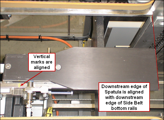
1 |
Toward downstacker flights |
0.25 |
0 |
Downstream edge of spatula is at the shear point. (Downstream edge of side belt bottom rails) |
|
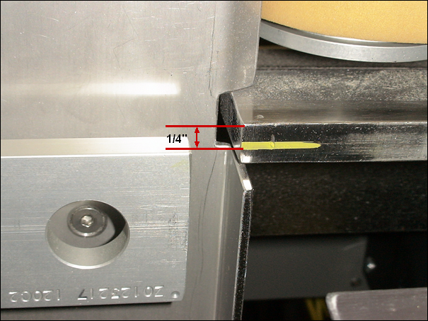
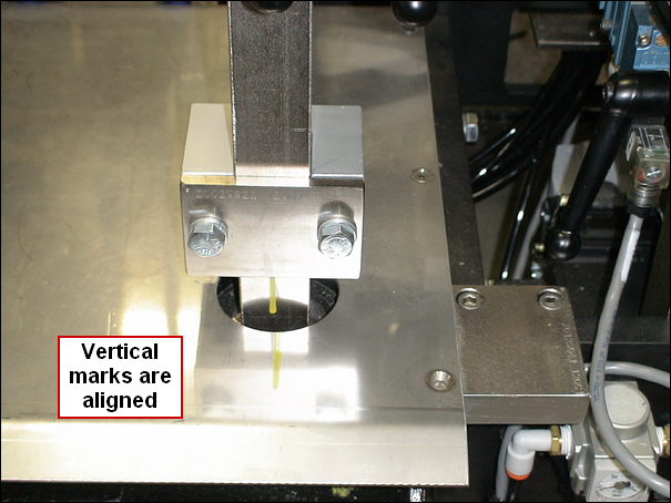
2 |
Down with product |
-24.375 |
0 |
Top of flight 1/4" below sheer point |
|
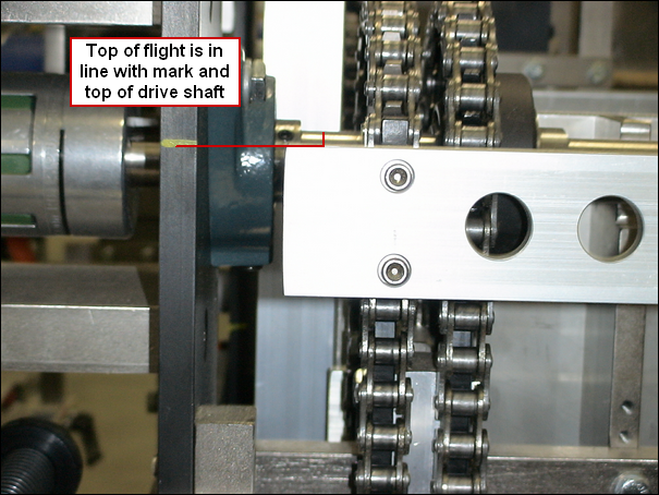
3 |
Down with product |
-24.375 |
30.95 |
Top of flight in line with the top of upper drive shaft |
|
4 |
Down with product |
-19 |
0 |
Top of flight 1/4" below sheer point |
|
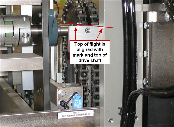
5 |
Down with product |
-18.875 |
30.827 |
Top of flight in line with the top of upper drive shaft |
|
6 |
Moving product downstream |
-1 |
0 |
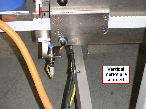
1" off of upstream hardstop (Located on upstream end of v-rail) |
|
7 |
Moving product downstream |
-1 |
0 |
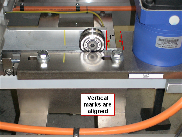
1" from the mechanical stop in the retracted position |
|
8 |
Funnel moving out of case |
-10 |
0 |
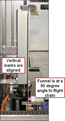
Funnel is 90 degrees to flight chain |
|
9 |
Funnel moving out of case |
-15 |
0 |
Funnel is 90 degrees to flight chain |
|
10 |
Tucking trailing flap |
-5 |
0 |
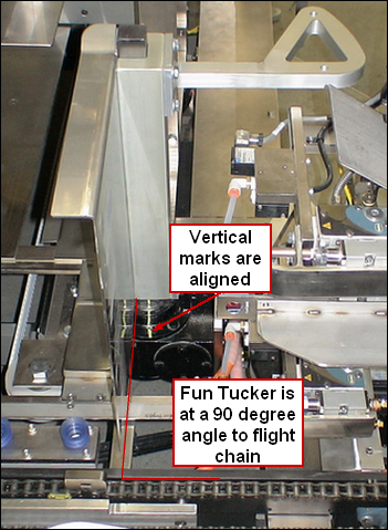
Tucker arm is 90 degrees to flight chain |
|
11 |
Tucking leading flap |
140 |
0 |
Tucker arm is 90 degrees to flight chain |
|
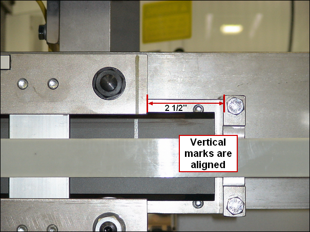
12 |
Toward palletizer |
34.53 |
32 |
2.5" from the downstream mechanical stop |
|
13 |
Down |
-1 |
0 |
1" from the mechanical stop in the retracted position |
|
14 |
Toward palletizer |
0.675 |
0 |
Leading edge of flight is aligned with fixed side of load chamber |
|
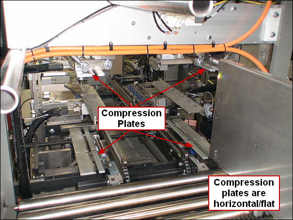
15 |
From horizontal to vertical |
-4 |
0 |
Compression plate is horizontal (open) |
|
16 |
From horizontal to vertical |
-2 |
0 |
Compression plate is horizontal (open) |
|
17 |
From horizontal to vertical |
-8 |
0 |
Compression plate is horizontal (open) |
|
18 |
From horizontal to vertical |
-3 |
0 |
Compression plate is horizontal (open) |
|
19 |
Moving towards operator side |
-7.625 |
0 |
Operator side face of flight is aligned with operator side of sheet metal backstop |
|
20 |
Tipping product |
-1 |
0 |
1 inch from the "up" mechanical stop |
|
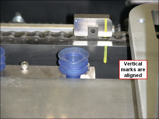
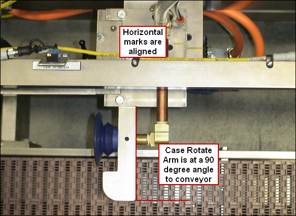
21 |
Turning case |
130 |
0 |
Vacuum cup arm is 90 degrees to conveyor |
|
|
|
|
|
|
|
|
|
|
|
|
|
|
|
|
|
|
|
|
|
|
|
|
|
|
|
|
|
|
|
|
|
|
|
|